

 Technical Information Power And Control Cables Power Appendixes CABLING ; Tools , procedure , accessories , laying and handling CABLE CLEATS
 صفحه CABLE CLEATS
CABLE CLEATS
Why use cable cleats for securing cables?
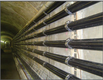
Cable cleats are designed to fix, retain and support cables. In addition, where short-circuit faults are anticipated, correct cleating will result in the containment of the cables during a fault and enable the circuit to be restored once the fault has been repaired.
When adjacent cables carrying three phase current suffer a short circuit fault, the induced magnetic fields result in the cables experiencing significant opposing forces, a safe installation requires well designed and thoroughly tested cable cleats.
Short circuits and short circuit testing :
Short circuit current is given either as a “peak” or an “rms” value. The peak current is the maximum current experienced by any of the phases and it occurs once within the first few milliseconds of the start of the fault.
The rms current is a calculated value for the initial cycles of the fault. The relationship between peak current and rms current varies from installation to installation.
The forces experienced by a cleat during a short circuit are a function of short circuit current, cleat spacing and the distance between the cable centres (in the case of trefoil arrangements this is the cable diameter).
When comparing short circuit test results for different products all three factors must be taken into consideration to compare the relative aggressiveness of the tests. The following formula taken from the draft Cenelec standard for cable cleats prEN 50368 calculates the force experienced by a cleat with cables arranged in trefoil formation .
 |
 |
IEC Standard for CABLE CLEATS
IEC 61914 (2009) : Cable cleats for electrical installations
This International Standard specifies requirements and tests for cable cleats and intermediate restraints used for securing cable in electrical installations.
Cable cleats provide resistance to electromechanical forces where declared.
This standard includes cable cleats that rely on a mounting surface specified by the manufacturer for axial and/or lateral retention of cables.
Classification :
A) According to material (part 6.1)
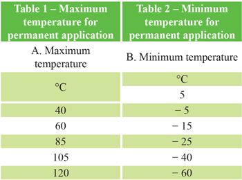
B) According to maximum and minimum temperature (part 6.2)
C) According to resistance to impact (part 6.3)
D) According to type of retention or resistance to electromechanical forces or both (part 6.4)
E) According to environmental influences (part 6.5)
A) According to material
6.1.1 Metallic
6.1.2 Non-metallic
6.1.3 Composite
B) According to maximum and minimum temperature
|
|
 |
|
C) According to resistance to impact 6.3.1 Very light 6.3.2 Light 6.3.3 Medium 6.3.4 Heavy 6.3.5 Very heavy |
D) According to type of retention or resistance to electromechanical forces or both 6.4.1 With lateral retention 6.4.2 With axial retention 6.4.3 Resistant to electromechanical forces, withstanding one short circuit 6.4.4 Resistant to electromechanical forces, withstanding more than one short circuit |
|
E) According to environmental influences 6.5.1 Resistant to ultraviolet light for non-metallic and composite components 6.5.1.1 Not declared 6.5.1.2 Resistant to ultraviolet light 6.5.2 Resistant to corrosion for metallic and composite components 6.5.2.1 Low 6.5.2.2 High |
|
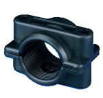
Examples of CABLE CLEATS for Flat and Trefoil formation
|
Flat Formation |
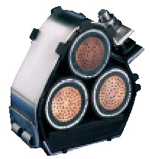
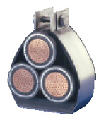
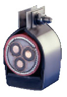
Trefoil Formation |
||
 |
 |
 |
|
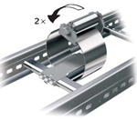
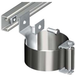
| Most common cleats (IEC 148/09) IEC 61914(2009) / fastening on ladder | |||
 |
 |
 |
 |
|
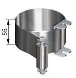
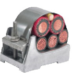
Aluminium Trefoil Cleats ......... More examples of CABLE Cleats , Clamps , Hangers |
|||
 |
 |
 |
 |
|
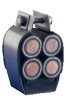
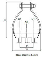
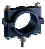
Trefoil and single cable Cleats These cable cleats are available for trefoil and single cable applications where the highest levels of short circuit withstand are required. The unique patented design allows rapid installation. Manufactured in type 316 stainless steel the Emperor cleats offer ultimate protection against the harshest environmental conditions. To protect and cushion the cables during short circuit conditions, the cleat is supplied with an integral LSF Zero Halogen Polymeric liner and base pad. Recommended fixing methods include using either two 10mm bolts or a single 12mm bolt (available as extras). A Retention Strap can be fitted between wider spaced cleats for a more economical installation. |
|||
 |
 |
 |
 |
 |
 |
 |
|
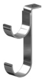
| Cable clamps | Cable Hanger | ||
 |
 |
 |
 |